소형 원심 송풍기에서 송풍기 서징이 발생하는 원인은 무엇이며 엔지니어는 어떻게 불안정한 기류를 방지할 수 있습니까?
August 31 , 2026소형 원심 송풍기는 전자 장비, 의료 기기, 가전 제품, 냉동 시스템, 배터리 장비, 충전 장비, 제어 캐비닛, 환기 시스템 및 기타 소형 설비에 널리 사용됩니다. 이러한 송풍기는 종종 제한된 공간 내에 설치되므로 엔지니어는 풍량, 정압, 소음, 전력 소비, 크기 및 신뢰성 간의 균형을 맞춰야 합니다.
많은 경우, 소형 송풍기 선택은 간단해 보입니다. 엔지니어는 필요한 풍량을 제품 사양서에 기재된 최대 풍량과 비교하여 충분한 용량을 가진 모델을 선택할 수 있습니다. 그러나 송풍기가 전체 장비 시스템에 설치된 후 실제 풍량 성능은 예상과 크게 다를 수 있습니다.
이유는 간단합니다. 송풍기는 독립적으로 작동하지 않기 때문입니다.
송풍기는 공기 덕트, 필터, 방열판, 통풍구, 그릴, 굴곡부, 좁은 통로, 열교환기 및 기타 구성 요소로 인해 발생하는 저항을 극복해야 합니다. 이 저항이 너무 커지면 송풍기의 작동 지점이 이상적인 범위에서 벗어나게 됩니다. 그 결과 공기 흐름이 크게 감소하고, 압력이 변동하며, 비정상적인 소음이나 진동이 발생할 수 있습니다.
특정 조건에서 송풍기와 연결된 공기 흐름 시스템 간의 상호 작용으로 인해 송풍기 서징 또는 흐름 불안정성으로 일반적으로 설명되는 불안정한 작동 상태가 발생할 수 있습니다.
대형 산업용 원심 송풍기의 경우, 서지 현상은 강한 압력 및 유량 진동을 동반하는 심각한 공기역학적 현상입니다. 그러나 소형 장비에 사용되는 소형 원심 송풍기의 경우, 이러한 현상은 대개 심각하지 않습니다. 엔지니어는 대형 산업 시스템에서 나타나는 심각한 서지 현상을 경험하기 전에 높은 시스템 저항, 상당한 공기 흐름 감소, 압력 변동, 맥동 소음 또는 불안정한 공기 흐름과 같은 문제를 접할 가능성이 더 높습니다.
소형 송풍기가 장착된 장비를 설계할 때는 이러한 차이점을 이해하는 것이 중요합니다.
이 글에서는 소형 원심 송풍기에서 송풍기 서징이 무엇을 의미하는지, 과도한 시스템 저항이 불안정한 공기 흐름을 유발하는 이유, 엔지니어가 잠재적인 문제를 식별하는 방법, 그리고 적절한 송풍기 선택 및 공기 흐름 경로 설계를 통해 위험을 줄이는 방법에 대해 설명합니다.
송풍기 서징이란 무엇인가요?
송풍기 서징이란 송풍기에서 발생하는 공기 흐름과 압력이 비교적 안정적인 상태를 유지하지 못하고 변동하는 불안정한 공기역학적 상태를 말합니다.
이 현상은 송풍기 성능과 시스템 저항 간의 관계와 밀접한 관련이 있습니다.
모든 원심 송풍기는 성능 곡선을 가지고 있습니다. 이 곡선은 일반적으로 정압 변화에 따른 풍량 변화를 보여줍니다. 시스템 저항이 낮을 때는 송풍기가 비교적 높은 풍량을 공급할 수 있습니다. 시스템 저항이 증가하면 송풍기는 더 높은 압력에서 작동하는 동안 풍량은 감소합니다.
완전한 장비 시스템 또한 고유한 저항 특성을 가지고 있습니다.
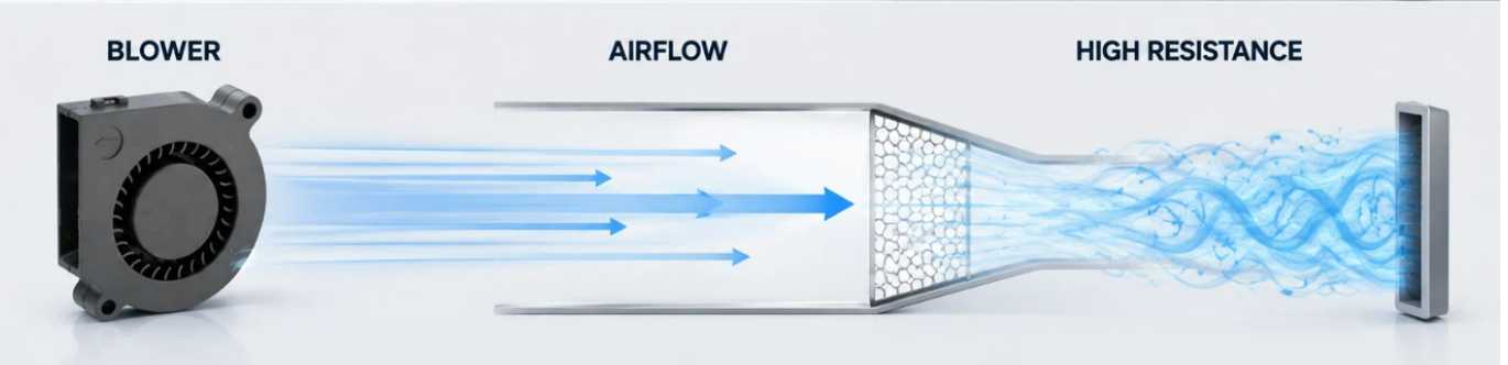
예를 들어, 전자 기기 내부에 설치된 소형 송풍기를 상상해 보세요. 공기는 흡입구를 통해 들어가 송풍기를 통과하고, 좁은 내부 통로를 지나 방열판을 가로지른 후 작은 통풍구를 통해 배출됩니다.
각 부분은 저항을 발생시킵니다.
공기 흐름 경로가 비교적 개방되어 있으면 송풍기는 적절한 풍량을 유지하면서 안정적인 작동을 할 수 있습니다.
콘센트가 막히면 시스템 저항이 증가합니다.
필터가 더러워지면 저항이 다시 증가합니다.
방열판에 먼지가 쌓이면 저항이 더욱 증가할 수 있습니다.
결국 송풍기는 작동 범위의 일부 구간, 즉 공기 흐름이 매우 낮아지고 공기역학적 거동이 불안정해지는 구간으로 밀려날 수 있습니다.
송풍기 설계 및 시스템 구성에 따라 공기 흐름의 맥동, 압력 변동, 소음 변화, 진동 또는 기타 불안정한 동작이 발생할 수 있습니다.
따라서 엔지니어는 송풍기 서지 현상을 단순히 송풍기 모터 내부의 문제로만 생각해서는 안 됩니다.
이는 대개 송풍기와 전체 공기 흐름 시스템 간의 상호 작용의 결과입니다.
소형 송풍기에서 송풍 출력 급증 현상이 흔한가요?
이는 장비 설계자들에게 중요한 질문입니다.
소형 원심 송풍기는 공기역학적 불안정성을 겪을 수 있지만, 엔지니어는 소형 송풍기 응용 분야에 "서징"이라는 용어를 적용할 때 주의해야 합니다.
대형 산업용 원심 압축기 및 대형 공정용 송풍기는 상당한 유량 역전 및 압력 진동을 수반하는 강한 서지 현상을 겪을 수 있습니다. 전자 제품이나 가전 제품 냉각에 사용되는 소형 DC 송풍기는 일반적으로 훨씬 낮은 유량과 더 작은 시스템 용량에서 작동합니다.
그 결과, 증상이 종종 다르게 나타납니다.
소형 송풍기는 다음과 같은 문제를 겪을 수 있습니다.
공기 흐름 감소
더 높은 정압
맥동하는 공기 흐름
공기역학적 소음의 변화
진동 증가
변동하는 모터 부하
냉각 성능 저하
이러한 현상은 고전적인 산업적 의미의 심각한 서지 현상이 아니더라도 시스템 저항이 과도하여 발생할 수 있습니다.
따라서 마케팅 및 엔지니어링 커뮤니케이션 측면에서 볼 때, 소형 원심 송풍기는 불리한 시스템 조건에서 불안정한 기류 또는 서지 현상과 같은 동작을 보일 수 있다고 설명하는 것이 더 정확합니다.
이러한 구분은 기술적 논의의 신뢰성을 높여줍니다.
또한, 송풍기를 선택할 때 단순히 풍량이 가장 높은 제품을 찾는 것만이 아니라는 점을 고객에게 이해하는 데 도움이 됩니다.
시스템 저항이 그토록 중요한 이유
시스템 저항은 소형 원심 송풍기의 실제 성능에 영향을 미치는 가장 중요한 요소 중 하나입니다.
송풍기 사양에는 최대 풍량 값이 명시될 수 있습니다. 그러나 최대 풍량은 일반적으로 특정 시험 조건에서 측정되며, 송풍기가 매우 적은 저항에 직면할 때 발생할 수 있습니다.
실제 장비는 다릅니다.
송풍기가 설치되면 공기는 전체 공기 흐름 경로를 따라 이동해야 합니다.
필터는 저항을 발생시킵니다.
격자는 저항을 발생시킵니다.
방열판은 저항을 발생시킵니다.
좁은 덕트는 저항을 발생시킵니다.
긴 덕트는 저항을 발생시킵니다.
급격한 굽힘은 저항을 발생시킵니다.
작은 콘센트는 저항을 발생시킵니다.
이러한 효과들이 복합적으로 작용하면 상당한 영향을 미칠 수 있습니다.
이러한 이유로 엔지니어는 최대 유량만을 고려하는 대신 공기 흐름과 정압의 관계를 살펴보아야 합니다.
예를 들어, 높은 자유 공기 유량을 광고하는 송풍기라도 밀집된 냉각 구조물에 연결되면 실제 공기 유량은 상당히 감소할 수 있습니다.
이는 특히 소형 장비에서 중요한데, 설계자가 공기 통로를 위한 공간을 제한적으로 확보해야 하는 경우가 많기 때문입니다.
공기 흐름 경로가 좁아지면 압력 강하가 급격히 증가할 수 있습니다.
시스템 저항이 너무 높아지면 송풍기는 작동 시간의 대부분을 낮은 풍량과 높은 압력 상태에서 보낼 수 있습니다.
이는 냉각 성능을 저하시키고 불안정한 공기역학적 거동을 유발할 수 있습니다.
자유 공기 흐름과 실제 작동 흐름의 차이점
송풍기 선택 시 가장 흔한 실수 중 하나는 자유 공기 유량 값만 비교하는 것입니다.
자유 공기 흐름은 외부 저항이 최소화된 상태를 나타냅니다.
실제 장비는 거의 완전히 제한 없는 조건에서 작동하지 않습니다.
송풍기를 사용하여 방열판에 공기를 불어넣는 냉각 방식을 생각해 보십시오.
방열판의 핀 간격이 좁으면 공기 흐름 저항이 상당할 수 있습니다.
이제 먼지 필터를 추가하세요.
그다음 좁은 콘센트를 추가하세요.
그다음 공기 통로에 굽힘 부분을 두 개 추가하세요.
최종 시스템 저항은 최초 계산치보다 훨씬 높을 수 있습니다.
송풍기는 이러한 모든 압력 손실을 극복해야 합니다.
따라서 실제 공기 흐름량은 개방된 공기 조건에서 표시된 수치보다 훨씬 낮을 수 있습니다.
따라서 전문가가 송풍기를 선택할 때는 항상 예상 시스템 압력을 고려해야 합니다.
소형 원심 송풍기에서 불안정한 공기 흐름이 발생하는 원인은 무엇입니까?
불안정한 기류에는 여러 요인이 작용할 수 있습니다.
첫 번째는 과도한 콘센트 제한입니다.
배출구 크기가 너무 작으면 송풍기는 시스템을 통해 공기를 이동시키기 위해 더 높은 압력을 발생시켜야 합니다.
두 번째는 공기 통로의 크기가 작다는 것입니다.
좁은 통로는 공기 속도를 증가시키고 압력 손실을 초래합니다.
세 번째는 필터 저항이 과도하다는 점입니다.
먼지가 쌓이면 필터의 성능은 더욱 저하됩니다.
네 번째는 흡입구 설계가 부실하다는 점입니다.
A blower needs a suitable air supply. If the inlet is partially blocked or airflow enters the impeller unevenly, aerodynamic performance may deteriorate.
The fifth is excessive duct bending.
Sharp bends close to the blower can create turbulence and uneven velocity distribution.
The sixth is improper blower selection.
A blower that is too small may not have sufficient pressure capability for the application.
A blower that is too large may create excessive pressure and force the system to use restrictive control methods.
The seventh is changing operating conditions.
A system may work well during initial testing but become less stable after filters become dirty or when equipment configuration changes.
Why Small Blower Size Does Not Mean Simple Airflow Design
Because small blowers occupy very little physical space, designers sometimes assume that airflow design is also simple.
In reality, compact systems can be more challenging.
A large industrial ventilation system may have sufficient space for smooth ducts, gradual transitions, large filters, and appropriately sized outlets.
A compact electronic device may have only a few centimeters of available space.
The designer may need to route air around circuit boards, heat sinks, batteries, cables, brackets, and structural components.
This creates many local restrictions.
A blower may have excellent performance when tested alone, but the same blower can perform very differently after installation.
Therefore, compact blower applications require careful attention to the complete airflow path.
How To Recognize Potential Blower Instability
Engineers and maintenance personnel can look for several warning signs.
The first is unusual airflow fluctuation.
If the equipment operates under a stable thermal load but airflow repeatedly changes, the airflow path should be inspected.
The second is pressure fluctuation.
A pressure sensor can help identify changes in system pressure that may not be obvious from airflow measurements alone.
The third is unusual noise.
A small blower operating normally should produce relatively consistent aerodynamic noise. Pulsating or changing noise can indicate turbulence, excessive restriction, or unstable airflow.
The fourth is increased vibration.
Aerodynamic instability can create changing forces on the impeller and housing.
The fifth is reduced cooling performance.
If electronic components become hotter even though blower speed has not changed, system resistance or airflow restriction may have increased.
The sixth is changing motor current.
Changes in aerodynamic loading can affect the electrical load of the motor.
These symptoms should be evaluated together rather than individually.
Does Higher RPM Always Solve The Problem?
Increasing blower speed can increase airflow and pressure, but it should not automatically be treated as the solution.
Suppose a filter is becoming blocked.
The equipment begins to experience reduced airflow.
An operator increases blower speed.
Airflow improves temporarily.
However, the filter remains blocked.
The blower now operates at a higher speed and may consume more power while generating higher pressure.
If the system resistance continues increasing, the operating condition may eventually become unfavorable again.
Therefore, higher speed can compensate for some operating changes, but it cannot replace proper airflow-path design and maintenance.
Engineers should always determine why airflow is declining before simply increasing speed.
Selecting The Right Blower Performance
For small centrifugal blowers, the most important selection information includes airflow, static pressure, operating voltage, speed, noise, dimensions, power consumption, operating temperature, and expected service life.
Among these parameters, the airflow-pressure relationship is particularly important.
The required operating point should be identified first.
For example, if the equipment requires a certain airflow while overcoming a defined static pressure, the selected blower should be able to provide that combination under the actual operating conditions.
This is much more meaningful than selecting a blower simply because its maximum airflow is higher than the required value.
Engineers should also consider the operating range.
If the equipment can experience changes in filter condition, temperature, valve position, or airflow demand, the blower should maintain acceptable performance across those conditions.
40mm Blower FanApplications And Airflow Stability
A 40mm blower fan is typically associated with compact equipment where installation space is limited.
Such small blowers can be useful for localized cooling inside electronic devices, control systems, instruments, communication equipment, and other compact assemblies.
However, their small size means that the airflow path can have a relatively large influence on total system resistance.
A small outlet that appears acceptable visually may represent a significant restriction relative to the blower's available airflow area.
Likewise, a narrow internal channel may consume a large portion of the available pressure.
Therefore, when designing a system around a 40mm blower fan, engineers should evaluate the complete airflow path rather than only the blower itself.
The inlet area, outlet area, duct length, bends, filters, and heat dissipation components should all be considered.
100mm Blower FanApplications
A 100mm blower fan provides more installation flexibility than extremely compact blowers in some applications and may be selected when greater airflow or pressure capability is required.
However, larger physical size does not automatically eliminate airflow instability.
A 100mm blower fan can still operate under excessive system resistance if the connected duct, filter, heat exchanger, or outlet is improperly designed.
The same selection principle therefore applies.
Engineers should match the blower to the actual system operating point.
The objective is stable airflow rather than simply maximum airflow.
Blower 5015And Compact Cooling Design
A blower 5015 is an example of the type of compact blower format that can be considered for space-constrained cooling applications.
When using compact blowers of this type, designers should pay particular attention to the relationship between blower dimensions and airflow-path dimensions.
A compact blower may fit easily into the equipment, but the surrounding structure can still restrict airflow.
For example, placing the blower directly against a narrow wall or mounting bracket may reduce the effective inlet area.
Similarly, connecting the outlet to a narrow passage may increase pressure loss.
These details can influence actual performance more than the nominal blower dimensions suggest.
How Inlet Design Affects Blower Performance
The blower inlet is often overlooked.
Air should be able to enter the blower smoothly and reasonably uniformly.
If the inlet opening is partially blocked, the blower may have to operate with an uneven velocity distribution.
A sharp bend immediately before the inlet can also create turbulence.
In compact equipment, engineers may need to position the blower close to other components because of space limitations.
However, leaving adequate inlet clearance can improve airflow quality.
The inlet grille should also provide sufficient open area.
A decorative grille may look attractive but create unnecessary pressure loss if its open area is too small.
How Outlet Design Affects System Resistance
The outlet is equally important.
A blower may generate sufficient pressure, but if the outlet cannot pass the required airflow, system resistance will increase.
The outlet should be appropriately sized.
Sudden contractions should be avoided where possible.
Sharp changes in direction should be minimized.
If a protective grille is required, its open area should be evaluated.
If a filter is installed at the outlet, its pressure drop should be included in the system calculation.
These small design decisions can have a significant effect on the final operating point.
Filters And Their Impact On Blower Operation
Filters are important for protecting equipment from dust, but they inevitably create pressure loss.
A new filter may have relatively low resistance.
After extended operation, dust accumulation can increase pressure drop.
This means the blower operating point can gradually change over time.
A cooling system that performed well during initial testing may therefore deliver less airflow several months later.
For equipment requiring stable thermal performance, filter condition should be included in the maintenance plan.
Engineers should also specify the acceptable filter pressure drop rather than treating filtration as an isolated component.
Heat Sinks Can Also Create Significant Resistance
Heat sinks are widely used in electronic cooling systems.
While a heat sink improves heat transfer, closely spaced fins can restrict airflow.
If the blower must force air through a dense fin structure, static pressure requirements increase.
The thermal engineer should therefore consider both heat transfer and pressure loss.
A heat sink with extremely dense fins may provide a large heat transfer surface but require more blower pressure.
A slightly different fin spacing may reduce pressure loss while still providing adequate thermal performance.
The best solution is usually a balance between thermal performance and airflow resistance.
The Importance Of System Testing
Calculations are important, but prototype testing is often necessary.
A small blower should ideally be tested inside the actual or representative equipment.
Testing should measure airflow, pressure, temperature, noise, vibration, and motor electrical parameters where appropriate.
The equipment should be tested under different thermal loads.
Minimum, normal, and maximum operating conditions should be evaluated.
If the system uses a filter, test both clean and representative loaded conditions when practical.
If the blower uses speed control, the complete control range should also be tested.
This approach allows engineers to identify problems before mass production.
How Engineers Can Reduce Surge Risk
The first step is to reduce unnecessary system resistance.
Use appropriately sized airflow channels.
Avoid unnecessary bends.
Provide adequate inlet and outlet areas.
Select filters with suitable pressure-drop characteristics.
Avoid excessive restrictions around heat sinks.
Choose the blower based on the actual airflow-pressure requirement.
Provide sufficient operating margin.
Use appropriate speed control when necessary.
Monitor system performance during operation.
Maintain filters and airflow paths.
These measures can significantly improve airflow stability.
Should Engineers Choose A Higher Pressure Blower?
Sometimes a higher pressure blower is appropriate.
If the system contains dense heat sinks, long ducts, filters, or other restrictive components, the blower needs enough pressure capability to maintain the required airflow.
However, selecting the highest pressure blower available is not always the best solution.
The blower should be matched to the system.
Too little pressure capability results in insufficient airflow.
Excessive pressure capability may increase noise, power consumption, and the need for restrictive control.
The correct solution is the blower that can provide the required airflow at the required static pressure while operating within a suitable region of its performance curve.
How Speed Control Can Help
Speed control can help compensate for changes in cooling demand.
When thermal load increases, blower speed can be increased within the permitted operating range.
When thermal load decreases, speed can be reduced.
This can improve energy efficiency and reduce unnecessary noise.
However, the control system should have defined operating limits.
It should not continuously command the blower into an unstable region.
For critical equipment, pressure or airflow feedback can be used to improve control accuracy.
The Role Of Motor And Impeller Design
Although system resistance is extremely important, blower construction also influences stability.
Impeller geometry determines how air is accelerated and pressurized.
Housing geometry affects the airflow path.
Motor speed affects pressure and airflow capability.
Impeller balance affects vibration.
Bearing quality influences mechanical reliability.
Material selection affects temperature resistance and structural stability.
Therefore, engineers should consider both aerodynamic performance and mechanical design when evaluating a blower.
Why Noise Can Be An Early Warning Sign
Noise is often one of the first things that users notice.
A change in sound may indicate increased turbulence or unstable airflow.
For compact equipment, noise is particularly important because users may be close to the product.
If a blower becomes noticeably louder after installation, engineers should check whether the airflow path is causing excessive pressure loss.
The noise may not be caused by the blower itself.
A narrow outlet, grille, duct bend, or turbulent transition can create significant additional aerodynamic noise.
Why Vibration Should Not Be Ignored
Vibration in a small blower can have several causes.
Mechanical imbalance is one possibility.
Bearing problems are another.
Improper mounting can also increase vibration.
However, aerodynamic instability should also be considered.
If vibration increases together with airflow fluctuation and changing noise, the system should be evaluated as a whole.
Replacing the blower without correcting the airflow restriction may not solve the problem.
Designing For Long-Term Reliability
A blower that performs well on the first day should continue performing well months or years later.
Long-term reliability requires consideration of dust accumulation, temperature, filter loading, component aging, changing operating conditions, and maintenance access.
The airflow system should therefore be designed with maintenance in mind.
Filters should be accessible.
Air channels should not be unnecessarily narrow.
Critical components should not be placed directly in front of the inlet.
Cleaning should be practical.
Sensors should be positioned where they can provide useful information.
These design details can significantly improve the long-term stability of the cooling system.
A Practical Troubleshooting Process
When a small blower system begins showing unstable airflow, engineers can follow a structured troubleshooting process.
First, confirm whether the required airflow and thermal load have changed.
Second, inspect the inlet.
Third, inspect the outlet.
Fourth, check filters and grilles.
Fifth, inspect heat sinks and ducts.
Sixth, measure static pressure.
Seventh, measure actual airflow.
Eighth, compare the measured operating point with the blower performance curve.
Ninth, check motor speed and electrical current.
Tenth, inspect mounting, vibration, and mechanical condition.
This process is more reliable than immediately replacing the blower.
Working With A Professional Blower Manufacturer
For equipment manufacturers, early communication with the blower supplier can simplify product development.
Instead of providing only the desired blower dimensions, engineers should provide the actual application requirements.
Useful information includes required airflow, estimated static pressure, operating voltage, available installation space, operating temperature, noise requirements, expected operating hours, and environmental conditions.
The blower manufacturer can then recommend a suitable performance range.
For customized applications, prototype testing can further improve confidence.
This approach can help prevent the common problem of selecting a blower according to dimensions first and discovering later that the actual airflow is insufficient.
China Chungfo Fan And Small Blower Applications
Chungfo Fanfocuses on the development and production of cooling fans, centrifugal blowers, axial fans, cross-flow fans, and other air-moving products for different equipment applications.
For compact blower applications, the selection process should begin with the complete airflow requirement rather than a single dimensional parameter.
Airflow, static pressure, voltage, speed, noise, operating temperature, installation conditions, and expected service life all need to be considered.
This application-oriented approach is especially important when a small blower is installed in a compact enclosure.
The blower itself may occupy only a small area, but the surrounding airflow structure can strongly influence its actual performance.
By evaluating the complete system, engineers can better balance cooling performance, energy consumption, noise, installation space, and reliability.
Final Thoughts
Small centrifugal blowers are highly useful for compact cooling and ventilation applications, but their performance depends strongly on the system in which they are installed.
Blower surging in the classical industrial sense is not necessarily the most common problem for small electronic or appliance blowers. However, unstable airflow, high system resistance, pressure fluctuation, pulsating noise, vibration, and significant airflow reduction are all important issues that engineers should understand.
The key lesson is that maximum airflow is not enough for blower selection.
The real operating point depends on both the blower and the system.
A small blower connected to a restrictive airflow path may deliver much less airflow than expected. Increasing speed may temporarily compensate for the problem, but it does not eliminate the underlying resistance.
Engineers should therefore evaluate the complete airflow path, including the inlet, outlet, filters, ducts, heat sinks, grilles, bends, and other components.
The blower should be selected according to the required airflow and static pressure, and the system should be validated under realistic operating conditions.
For compact applications using products such as a 40mm blower fan, a 100mm blower fan, or a blower 5015, careful system design is particularly important because limited installation space can create significant airflow restrictions.
Ultimately, stable blower operation comes from matching the blower to the real system rather than simply selecting the largest airflow specification.
When blower selection, airflow-path design, testing, control, and maintenance are considered together, engineers can achieve more reliable cooling performance, lower unnecessary noise, better energy efficiency, and longer equipment life.
FAQ
What is blower surging?
Blower surging is an unstable airflow condition in which pressure and airflow fluctuate instead of remaining relatively stable. In small blower applications, engineers may more commonly encounter airflow instability caused by excessive system resistance.
Can a small centrifugal blower experience surge?
Yes, small centrifugal blowers can experience aerodynamic instability under unfavorable operating conditions. However, the behavior is often less severe than the classical surge phenomenon associated with large industrial centrifugal machines.
What usually causes unstable airflow in a small blower system?
Common causes include excessive outlet restriction, narrow ducts, dirty filters, dense heat sinks, poor inlet design, sharp bends, improper blower selection, and changing operating conditions.
Does a higher RPM always solve low airflow?
No. Increasing speed can increase airflow and pressure, but it cannot remove a blocked filter, undersized duct, or restricted outlet. The underlying system resistance should be investigated first.
Why is static pressure important for small blower selection?
Static pressure indicates how much resistance the blower must overcome. A blower with a high free-air airflow rating may provide much less actual airflow when connected to a restrictive system.
Can a 40mm blower fan be used for high-resistance applications?
It can be used when its performance curve provides sufficient airflow at the required static pressure. The compact size alone does not determine whether it is suitable.
Is a 100mm blower fan automatically more stable?
Not necessarily. A larger blower may provide greater airflow or pressure capability, but stability still depends on the relationship between the blower and the connected airflow system.
What should engineers check when blower noise suddenly increases?
They should inspect the inlet, outlet, filters, ducts, grilles, heat sinks, mounting structure, and operating point. Increased noise may result from turbulence or excessive system resistance rather than a defective blower.
Can a blower 5015 be used in compact electronic equipment?
Compact blower formats can be suitable for electronic equipment when their airflow and pressure characteristics match the application's requirements. Engineers should evaluate the complete airflow path before final selection.
How can engineers reduce the risk of unstable airflow?
Engineers can reduce unnecessary system resistance, provide adequate inlet and outlet areas, select suitable filters, design smoother airflow paths, choose the blower according to the required airflow and static pressure, and validate the system under realistic operating conditions.
Should a blower always be selected with the highest possible airflow?
No. Maximum airflow is only one parameter. The blower should provide the required airflow at the actual system static pressure while operating within an appropriate and stable range.
Can dirty filters affect blower performance?
네. 먼지가 쌓이면 필터 저항이 증가하여 공기 흐름이 감소하고 송풍기 작동 지점이 변경될 수 있습니다. 안정적인 성능을 유지하려면 정기적인 점검 및 교체가 중요합니다.
송풍기 설치 후 성능 테스트를 해야 하는 이유는 무엇입니까?
실제 장비는 개방된 공기 중에서 측정할 때는 존재하지 않을 수 있는 저항을 발생시키기 때문입니다. 설치 환경에 따라 공기 흐름, 압력, 소음, 온도 및 전력 소비량이 크게 달라질 수 있습니다.
송풍기 추천을 요청할 때 엔지니어는 어떤 정보를 제공해야 할까요?
중요 정보에는 필요한 풍량, 정압, 작동 전압, 설치 치수, 작동 온도, 소음 요구 사항, 작동 주기, 환경 조건 및 예상 수명이 포함됩니다.
소형 원심 송풍기를 선택할 때 가장 중요한 원칙은 무엇입니까?
가장 중요한 원칙은 송풍기의 공기 흐름 및 압력 성능을 실제 시스템 작동 지점에 맞추는 것이지, 단순히 물리적 크기나 최대 공기 흐름만을 기준으로 제품을 선택하는 것이 아닙니다.